Overview
In this lesson, you will build on lesson 4, adding the facility to control the LEDs from your computer using the Arduino Serial Monitor. The serial monitor is the ‘tether’ between the computer and your Arduino – it lets you send and receive text messages, handy for debugging and also controlling the Arduino from a keyboard!

For example, you will be able to send commands from your computer to turn on LEDs.
In this lesson, you will use exactly the same parts and a similar breadboard layout as Lesson 4. So, if you have not already done so, follow lesson 4 now.
The Serial Monitor
Upload the following sketch to your Arduino. Later on, we will see exactly how it works.
/*
Adafruit Arduino - Lesson 5. Serial Monitor
*/

int latchPin = 5;
int clockPin = 6;
int dataPin = 4;

byte leds = 0;

void setup()
{
  pinMode(latchPin, OUTPUT);
  pinMode(dataPin, OUTPUT);
  pinMode(clockPin, OUTPUT);
  updateShiftRegister();
  Serial.begin(9600);
  while (! Serial); // Wait untilSerial is ready - Leonardo
  Serial.println("Enter LED Number 0 to 7 or 'x' to clear");
}

void loop()
{
  if (Serial.available())
  {
    char ch = Serial.read();
    if (ch >= '0' && ch <= '7')
    {
      int led = ch - '0';
      bitSet(leds, led);
      updateShiftRegister();
      Serial.print("Turned on LED ");
      Serial.println(led);
    }
    if (ch == 'x')
    {
      leds = 0;
      updateShiftRegister();
      Serial.println("Cleared");
    }
  }
}

void updateShiftRegister()
{
   digitalWrite(latchPin, LOW);
   shiftOut(dataPin, clockPin, LSBFIRST, leds);
   digitalWrite(latchPin, HIGH);
}
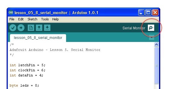
After you have uploaded this sketch onto your Arduino, click on the right-most button on the toolbar in the Arduino IDE. The button is circled below.

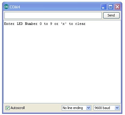
The following window will open.

This window is called the Serial Monitor and it is part of the Arduino IDE software. Its job is to allow you to both send messages from your computer to an Arduino board (over USB) and also to receive messages from the Arduino.
The message “Enter LED Number 0 to 9 or ‘x’ to clear” has been sent by the Arduino, and it is telling us what commands we can send to the Arduino which is either to send the ‘x’ (to turn all the LEDs off) or the number of the LED you want to turn on (where 0 is the bottom LED, 1 is the next one up right up to 7 for the top LED).
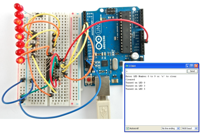
Try typing the following commands, into the top area of the Serial Monitor that is level with the ‘Send’ button. Press ‘Send’, after typing each of these characters: x 0 3 5
Typing x, will have no effect, if the LEDs are already all off, but as you enter each number, the corresponding LED should light and you will get a confirmation message from the Arduino board, so that the Serial Monitor will appear as shown below.

You can see that I am about to press send after entering ‘x’ again. Do this and all the LEDs will turn off.
Arduino Code
As you might expect, the sketch is based on the sketch used in lesson 4. So, we will just cover the new bits here. You will find it useful to refer to the full sketch in your Arduino IDE.
Firstly, in the ‘setup’ function, there are three new lines on the end:
void setup()
{
  pinMode(latchPin, OUTPUT);
  pinMode(dataPin, OUTPUT);
  pinMode(clockPin, OUTPUT);
  updateShiftRegister();
  Serial.begin(9600);
  while (! Serial); // Wait until Serial is ready - Leonardo
  Serial.println("Enter LED Number 0 to 7 or 'x' to clear");
}
Firstly, we have the command ‘Serial.begin(9600)’. This starts serial communication, so that the Arduino can send out commands through the USB connection. The value 9600 is called the ‘baud rate’ of the connection. This is how fast the data is to be sent. You can change this to a higher value, but you will also have to change the Arduio Serial monitor to the same value. We will discuss this later, but for now leave it at 9600.
The line beginning with ‘while’ ensures that there is something at the other end of the USB connection for the Arduino to talk to before it starts sending messages. Otherwise, the message might be sent, but not displayed. This line is actually only necessary if you are using an Arduino Leonardo, because the Arduino Uno automatically resets the Arduino board when you open the Serial Monitor, whereas this does not happen with the Leonardo.
The last of the new lines in ‘setup’ sends out the message that we see at the top of the serial monitor.
The ‘loop’ function is where all the action happens:
void loop()
{
  if (Serial.available())
  {
    char ch = Serial.read();
    if (ch >= '0' && ch <= '7')
    {
      int led = ch - '0';
      bitSet(leds, led);
      updateShiftRegister();
      Serial.print("Turned on LED ");
      Serial.println(led);
    }
    if (ch == 'x')
    {
      leds = 0;
      updateShiftRegister();
      Serial.println("Cleared");
    }
  }
}
Everything that happens inside the loop is contained within an ‘if’ statement. So unless the call to the built-in Arduino function ‘Serial.available()’ is ‘true’ then nothing else will happen.
Serial.available() will return ‘true’ if data has been sent to the Arduino and is there ready to be processed. Incoming messages are held in what is called a buffer and Serial.available() returns true if that buffer is Not empty.
If a message has been received, then its on to the next line of code:
char ch = Serial.read();This reads the next character from the buffer, and removes it from the buffer. It also assigns it to the variable ‘ch’. The variable ‘ch’ is of type ‘char’ which stands for ‘character’ and as the name suggests, holds a single character.
If you have followed the instructions in the prompt at the top of the Serial Monitor, then this character will either be a single digit number between 0 and 7 or the letter ‘x’.
The ‘if’ statement on the next line checks to see if it is a single digit by seeing if ‘ch’ is greater than or equal to the character ‘0’ and less than or equal to the character ‘7’. It looks a little strange comparing characters in this way, but is perfectly acceptable.
Each character is represented by a unique number, called its ASCII value. This means that when we compare characters using <= and >= it is actually the ASCII values that were being compared.
If the test passes, then we come to the next line:
int led = ch – '0';Now we are performing arithmetic on characters! We are subtracting the digit ‘0’ from whatever digit was entered. So, if you typed ‘0’ then ‘0’ – ‘0’ will equal 0. If you typed ‘7’ then ‘7’ – ‘0’ will equal the number 7 because it is actually the ASCII values that are being used in the subtraction.
Since that we know the number of the LED that we want to turn on, we just need to set that bit in the variable ‘leds’ and update the shift register.
bitSet(leds, led);
updateShiftRegister();
The next two lines write back a confirmation message to the Serial Monitor.
Serial.print("Turned on LED ");
Serial.println(led);
The first line uses Serial.print rather than Serial.println. The different between the two is that Serial.print does not start a new line after printing whatever is in its parameter. We use this in the first line, because we are printing the message in two parts. Firstly the general bit: ‘Turned on LED ‘ and then the number of the LED.
The number of the LED is held in an ‘int’ variable rather than being a text string. Serial.print can take either a text string enclosed in double-quotes, or an ‘int’ or for that matter pretty much any type of variable.
After the ‘if’ statement that handles the case, when a single digit has been handled, there is a second ‘if’ statement that checks to see if ‘ch’ is the letter ‘x’.
    if (ch == 'x')
    {
      leds = 0;
      updateShiftRegister();
      Serial.println("Cleared");
    }
If it is, then it clears all the LEDs and sends a confirmation message.
Other Things to Do
We sent the character to control the LEDs separately, by clicking send after each character. However, it will work just as well, if you send all the character commands in a single line. Try entering the following into the Serial Monitor and clicking ‘Send’:
x0246
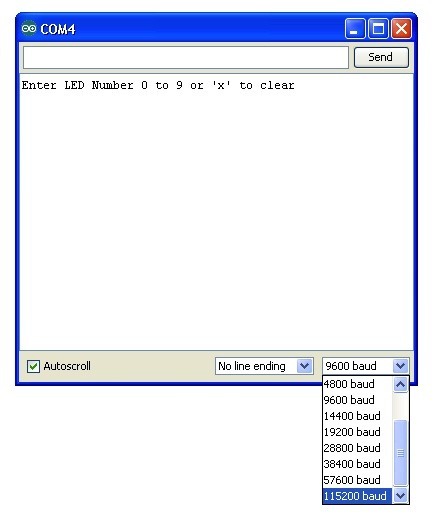
Now, lets see just how fast our Arduino can communicate. Change the baud rate in the sketch from 9600 to 115200 and upload it to the board again. Then after opening the Serial Monitor select 115200 from the drop-down list.

You should find that that everything still works. High speed communication not often necessary, so the baud rate of 9600 is often used, as many serial peripherals such as GPS modules will have this as a default baud rate, so it is something of a standard.
Also, try mismatching the baud rate – use Serial.begin(9600) and select 57600 in the dropdown menu, for example. See what it looks like? All garbled? That’s a mismatch. If you’re ever getting strange data in the Serial monitor, triple check your baud rates and make sure they match!
The Serial Monitor is also a great way of debugging a sketch that is misbehaving. Sometimes, when a sketch is not behaving how you think it should behave, placing Serial.println() statements in key places will help you see what is going on.
