Arduino Programming, from beginner to expert Part 1
A good workman always has good tools .
we will discover the tools at our disposal for electronic prototyping with Arduino. These tools will allow you to carry out assemblies and exercises in the course . Arduino is much more than just a programmable circuit board, it is a whole ecosystem that we will discover this part. Let’s get to work!
The Arduino ecosystem
Circuit boards + code + community ♥ = Arduino
If you’ve already heard of Arduino, it’s possible that you heard mention of the prototyping board of the same name: the Arduino board. In this course, however, we will learn about the whole Arduino Ecosystem. This consists of:
- A family of boards that can be used to make electronic assemblies. There are different sizes and colors and each has different features (below left, an Arduino UNO and, right, an Arduino Nano):

- Computer software, called the Arduino IDE (Integrated Development Environment), which allows us to send instructions to the board. This software allows you to type instructions in the Arduino programming language (which is very similar to the C language). This is the famous Arduino code which we’re going to discover this part. Here’s what the code looks like:

- Finally, there is a global Arduino community – these are people just like you, who create their own projects and upload the documentation (code and instructions) for them on the Internet (like the blog of the site arduino.cc).
— This means that there is a lot of information already available online as a free reference and source of inspiration!
The history of Arduino
Created in Ivrea, Italy, in the mid-2000’s, the idea behind Arduino was to create a circuit board that was easily programmable by non-experts.
They wanted this board to be modular (to make it versatile), low-cost (< €20) and open-source (meaning that the recipe for its creation is available for free on the Internet, so that people can take the plans and make their own variants). This formula has proven so successful that today tens of thousands of artists, designers, engineers, researchers, teachers and even commercial organisations use it to carry out incredible projects. Applications of Arduino include:
- Capturing and analyzing scientific data from sensors for educational, research or citizen appropriation purposes;
- Live shows – thanks to the many interaction features offered by Arduino, it is possible to create performances in VJing (DJ video), which generates real-time sound and visual effects from dancers’ movements;
- Digital art installations – Arduino allows for the realization of works of art which can interact independently with the public;
- Artisanal production of digital objects and low-cost machine tools in the perspective of a culture of technological appropriation that promotes DIY and organizing;
- Rapid prototyping of innovative projects using electronics, since Arduino facilitates easy and cheap experimentation before manufacturing;
- Fashion and textile design – several designers are exploring the possibilities offered by the integration of electronics in clothing (e-textiles);
To see more ideas for what you can do with Arduino, check out Arduino’s own project ideas website, Hackster.io’s Arduino page and this page from Circuitdigest.
Why Arduino?
The objective of this paragraph is to understand what is at the heart of many projects of digital manufacturing; I am talking about Arduino, an electronic platform that will allow us to prototype intelligent objects. An Arduino can be seen as a computer because their features and operations are very close. They have the same resources. As in computers, there are two types of memory. The ROM allows us to store the instructions that we want to see executed by Arduino. This memory is preserved even if the Arduino is no longer powered. The RAM stores the data that changes, which is called variable. Finally, we find a calculator that can process and execute the instructions. All these elements are contained in what is called a microcontroller. To program it, a USB socket allows you to send instructions from computer running software that is also called Arduino. This USB port will also power it. Once programmed, the electronic card can then be powered with a battery or an AC outlet. Let’s get a little closer to the subject. The holes on the edge of the Arduino are also called pins. That’s where it gets interesting. These are inputs that will allow us to connect sensors, LEDs, motors or expansion cards. These modules make it possible to add one or more features to an Arduino, such as connecting to the internet by wifi, 3G/GPRS or Bluetooth, displaying on LCD screens, operating motors, or controlling shutters, light or sound. In short, Arduino allows you to interact with just about everything around you and it doesn’t stop there. The best thing about this platform is that its ecosystem is open and free. The documentation, the code, libraries, electronic diagrams… it’s all available for free on the internet. That’s why we chose this platform for our course. To illustrate the infinite possibilities of Arduino, here are some projects powered by this electronic card: a plant that will water itself when it needs to, a box that tells you if the weather will be ok, another which tells you when your subway is coming, a jacket that lights up to give directions to the cyclist who is wearing it, a machine that prints in 3D, a connected cat food dispenser, an autonomous quadcopter, a robot printed in 3D. Pretty cool .
Software for writing and checking your code
Now you’re going to learn how to type code to tell Arduino what to do. There are some tools you need for this:
1. The Arduino IDE is the preferred tool to use with the Arduino board, as it allows you to upload code to your Arduino board via USB. This software requires installation on your Windows, Linux or Mac computer.
2. TinkerCad by Autodesk will allow you to test your code and electronic circuits, virtually! no software installation on your computer is required.
Installing the Arduino software
You are the proud owner of an Arduino board, and it’s nearly time to upload your first program! For this you will need to install the Arduino computer software (also called the IDE, which stands for Integrated Development Environment).
Tutorial
- Go to the official website (arduino.cc) and click on Downloads under the Software tab on the navigation bar.
- On the page that opens, click the version that corresponds to your operating system. In my case, I selected Mac OS X.
- Once the software is downloaded, click on the installer and follow the procedure (you must have administrator rights to install the drivers under Windows and Mac OS).
- Launch the software and open the Blink example code by clicking on File > Examples > 01. Basics > Blink.
- The Arduino IDE has a simple look and feel. The window you can see now has only a small number of buttons whose main functions are listed below:
- Once you’ve got the Blink example open, you should see the following code: /* Blink Light the LED for 1 second, then turn it off for 1 second.*/ // Number of the pin connected to the LED:
int led = 13; // the function runs once when you press reset or power the board void setup() { // initialize digital pin ‘led’ as an output. pinMode(led, OUTPUT); } // this code runs over and over again as long as there is power void loop() { digitalWrite(led, HIGH); // light LED (send 5V to the pin) delay(1000); // wait 1000ms = 1s digitalWrite(led, LOW); // turn off LED (0V to the pin) delay(1000); // wait another second } - Joy and jubilation, your development environment is ready. To understand all this in more detail, we invite you to consult the upcoming section about coding our first program. But before then, we are going to run through some basic electronics.
References
- Installing Arduino IDE by Sparkfun
- Official Arduino language reference by the Arduino team
- 7 best Arduino simulators for PC by WindowsReport
- Add-ons for Arduino (French) by Eskimon
- Mini reference for the Arduino language (French) by Xavier Hinault
Using the Arduino simulator (TinkerCad)
Thanks to simulators, you can make basic Arduino assemblies without even owning an Arduino board!
The main simulator we will use in this course is called TinkerCad Circuit. It is provided by the company Autodesk (it is free, but proprietary, i.e. not open source).
If you do not want to use a real Arduino for now, follow the tutorial below:
Tutorial
- First create or sign in to your Autodesk account (Note: this will be your own private account – it will not be linked with betechbrain.com or with this course in any way). We recommend the Chrome browser, which can provide the full function of the simulator.
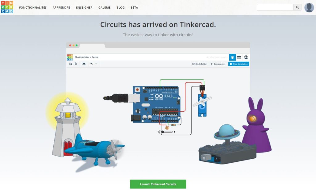
- Go to TinkerCad Circuit. Once you’ve logged in with your Autodesk details, you should have access to this page:
3. To create a new timeline, click on this button:

4. Fill in the necessary information on any the pages that open.
5. You should then have the choice to ‘Try Circuits’ or ‘Create New’. ‘Try Circuits’ takes you to a tutorial to guide you through the basics of TinkerCad and to show you its main capabilities, which takes a few minutes. If you already feel confident using TinkerCad, or if you’d prefer to find your own way, you can click ‘create circuit’ to get started right away.hen click “Create New!“
6.
Once the simulator loads, you will see a screen a little like this:
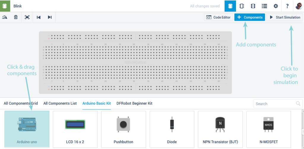
7. To place a component into your circuit assembly, you need to find it in the menu first. You can search for one by name or select it from the list.
8. When you’ve found the component you want, click once on the component in the list, then click on your assembly where you want to place it. For example, to start with an Arduino board, type ‘Arduino’ and the result ‘Arduino Uno R3’ should appear at the top.
Note that there are minor differences in the names of some components from the names we use in this course.
For example:
– Servos (covered later) are described as ‘micro servos’ in TinkerCad.
– Switches come in many different types, and the kind we use in this course is a pushbutton switch. This is the kind that is normally open (off) and makes a momentary contact when you press the button.
9. To create wires connecting the components you’ve placed, you can just click the contact
To change the wire placement, click on the wire first, and you can move the join points.
10. To send instructions to Arduino, click on it and then on Code editor.
11. Copy the following code and paste into the editor:
/*
  Blink
  Light the LED for 1 second,
  then turn it off for 1 second.
*/

// Number of the pin connected to the LED:
int led = 13;

// the function runs once when you press reset or power the board
void setup() {
// initialize digital pin 'led' as an output.
  pinMode(led, OUTPUT);
}

// this code runs over and over again as long as there is power
void loop() {
  digitalWrite(led, HIGH);   // light LED (send 5V to the pin)
  delay(1000);               // wait 1000ms = 1s
  digitalWrite(led, LOW);    // turn off LED (0V to the pin)
  delay(1000);               // wait another second
}
12. Finally, add a LED on pin 13, by dragging it from the right directly onto the pins 13 and GND on the Arduino:
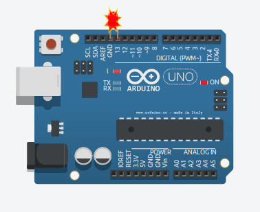
13. Click “Start Simulation” in the top right. Joy and jubilation – our Virtual LED flashes! We’re going to cover how the code and electronics works in the following sections.
14. That’s it for our basic crash-course – beyond this, the best way to figure out how to use TinkerCad is to have a go and try things out! There’s also plenty of support and tutorials on the TinkerCad website.
Arduino and breadboards
Below you will see a map that explains the connector pins found on an Arduino board. The most important things to note are:
- The USB connector (metal box on the top left) is where you plug in the cable to your computer
- Digital input pints along the top
- Multiple pins indicated ‘GND’ or ‘ground’ – these are all connected, and all at 0V (zero Volts).
- Analog pins along the bottom right – you will use these later.
- A 5V (five Volt) pin on the bottom in the middle – this is held by the board at +5V DC. (If you don’t know quite what this means, don’t worry – this will become clearer as we go through the course!)
- The 3.3V pin is used for some applications, but we will not be using it in this course.
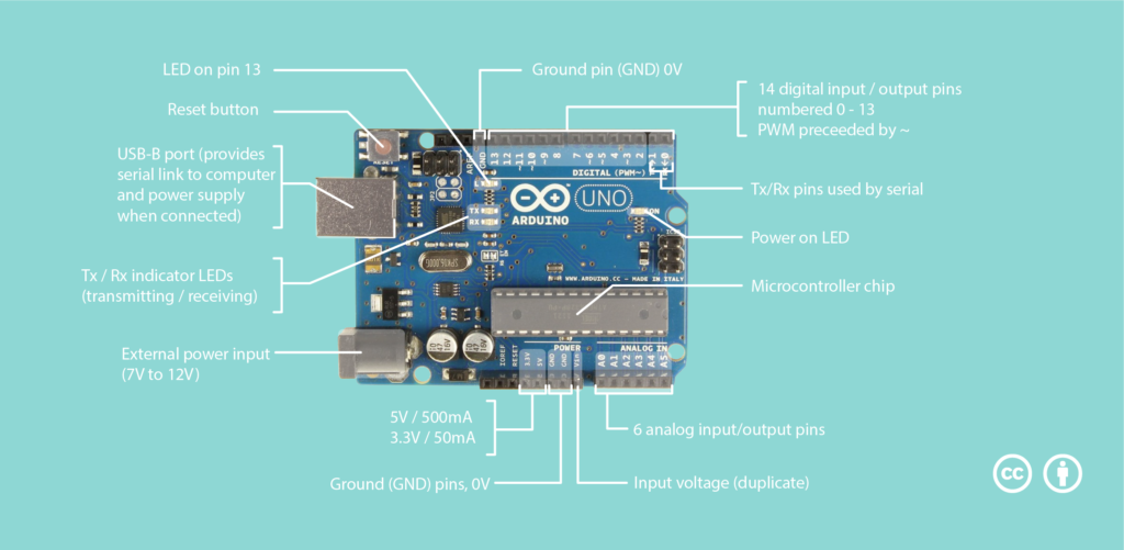
To avoid plugging directly into the Arduino, we will use a prototyping board or breadboard.
The principle of a breadboard
A breadboard is a plastic object with holes you can plug wires (jump leads) into. It’s designed as a way of building circuits quickly and neatly without needing to solder components permanently. To achieve this, some of the holes in the breadboard are electrically connected, and we’ll explain how. Here is a quick diagram that will help us understand.
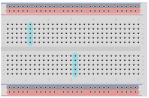
You can see that we have grouped certain regions of holes by highlighting them with colours.
The red and black areas correspond to the power lines. Often there are two lines like these at either end of the board, that allow you to connect your components to the necessary power supplies. By convention, we would connect the black line with a wire to the ground pin (‘GND’) on the Arduino board, which is at 0V. And then we’d hook up the red lineto the power supply (in this case, +5V). For the black and red regions in our breadboard diagram above, the holes are connected in horizontal lines. This means you have an easily accessible power line running the length of the board to plug your other components into.
Moving on to the middle part of the board: here, the holes are connected in the vertical direction. For example, in one of the blue rectangles, all the holes are linked together in that column. However, each column is separate from the others. This means that to connect one column to another, you would have to join them by plugging a wire into both.
Finally, there is a horizontal gap that cuts the board in half. This space also cuts the connection of the columns. Thus, in the above drawing, you can see that each column section has 5 holes that are connected vertically, but the top five is separate from the bottom five.
The gap in the middle of the breadboard is the width of a standard integrated circuits (IC’s) – a black microchip component with many legs. This means we can plug the IC into the breadboard, across the space in the middle, and can connect each leg to separate components.
If you want to play with examples of this, we recommend the software Fritzing (or TinkerCad) which allow you to make circuit diagrams in a simple and intuitive way.
Note that, on an Arduino board, the pins 0 and 1 (also called Rx and Tx) can be used to communicate with a computer. Because of this, it is impossible to use pins 0 and 1 and the USB upload capability at the same time. We therefore recommend that you do not use these pins to connect your LEDs, but instead focus on the other pins (Digital 2 to 13, and Analog 0 to 5)!
Basic laws of electricity
Before we make our first assembly and connect our first LED, it seems important to go over a few basic details about electricity.
Voltage and current
Every electrical circuit, no matter what size or complexity, deals with a current of electrons that is flowing in a loop. The magnitude or intensity of this electric current (I) is measured with the unit Ampères (A). (Note that there is a symbol for the quantity, I, and a separate symbol for the units, A)
To make electrons circulate through a circuit, you need a “driving force”. In electricity, this force is called voltage (V). The voltage is measured and expressed in Volts (V). (In this case, the quantity and the unit happen to have the same symbol!)
To visualise the difference between current and voltage, we can use an analogy of flowing water. The current of an electric circuit is like the quantity of water in a pipe. The voltage is like the water pressure. For a given pipe, the higher the pressure, the greater the flow of the water. Electricity is similar: the more the voltage increases, the greater the energy being delivered.
Resistance
Staying with our ‘water in a pipe’ analogy, we can look at another electrical quantity: resistance (R). For water, the friction between the liquid and the inside surface of the pipe acts to slow down the flow. All other things being equal, this friction-resistance becomes more significant the narrower the pipe, and the longer the pipe. And if we increase the pressure too much, the pipe breaks.
Electrical resistance is similar. The resistance (R) is measured and expressed in Ohms (Ω). Everything has a resistance – copper wire has a very low resistance but it’s still there. The smaller the diameter of the wire, the more resistance there is. The longer the wire, the more resistance there is. You may have already seen this in practice: if you try to pass too much current through a small electrical wire, the wire melts. Indeed, this is how a fuse works.
Ohm’s Law
Well, we already have three electrical phenomena to master: The voltage (volts), The current (Amps) and the resistance (ohms). These three are linked by a law of electricity known as Ohm’s law. The law is expressed in a very simple formula:
V = I × R
where:
- V : Voltage
- I : Current
- R : Resistance
The same law can be expressed in terms of the current or resistance respectively:
Because of this law, you will have to protect your LED with a resistance of between 200Ω et 1kΩ (it can go before or after the LED in series – external link).
First program: Blink
This is the first program that we will experiment with together! This sequence of instructions will switch an LED connected to pin 13 of the Arduino, on and off, once every second.
Arduino or simulator
In the Arduino IDE, the program Blink can be found in File→ Examples→ 01.Basics→ Blink. For the Arduino simulator, copy and paste this code into either the Codecast window above, or a Tinkercad window:
/*
  Blink
  Light the LED for 1 second,
  then turn it off for 1 second.
*/

// Number of the pin connected to the LED:
int led = 13;

// the function runs once when you press reset or power the board
void setup() {
// initialize digital pin 'led' as an output.
  pinMode(led, OUTPUT);
}

// this code runs over and over again as long as there is power
void loop() {
  digitalWrite(led, HIGH);   // light LED (send 5V to the pin)
  delay(1000);               // wait 1000ms = 1s
  digitalWrite(led, LOW);    // turn off LED (0V to the pin)
  delay(1000);               // wait another second
}
Assembly
Several people on the forum told us that they would like to be able to view the circuit used for this exercise. Here it is:

Remember that (unlike regular light bulbs) LEDs only work when connected in a particular direction – check that the – (minus) tab is connected to the GND (ground) pin of your Arduino. To remember this, just think: the shorter leg is the – (minus) leg. The other leg + (plus) must be connected to pin 13 which receives the current:

Explaining the code
At the end of each program, we will explain all the new code you used. As this is our first program, we have a few things to go over! (do not hesitate to click on the links below to reach the Arduino reference)
In this program, we have:
- Comments: These lines of text are for people, rather than machines – they are included to help you understand (or remember) how your program works, or to inform others. These lines are not read by Arduino, but they can be very important! There are two ways to create Comments lines:
/*
  Here is
  a comment across
  several lines
*/
// This is also a commentThe code:
- Declaring a variable: we want to create a new variable, give it a name, and store a number in it.
int led = 13;In this case, we have a variable called led which is going to be a number (the key word int stands for integer, which means a whole number) and we set it equal to the value 13.
- Blocks of code:
setupcontains all the instructions that are executed when the program starts. Thesetupfunction is only executed once, when the Arduino board is switched on or when you press the reset button. Theloopfunction contains instructions which are executed over and over again as long as the Arduino has power.
The two functions (blocks of code) inside setup and loop are necessary for every Arduino programme, even if they’re empty (i.e. even if they don’t contain instructions) – which would look like this:
void setup() { }
void loop() { }- Functions: are instructions that allow you to execute one or more actions. They are defined with:
- A name: the name of the function
- One or two inputs: variables passed into the function are called parameters or arguments. These arguments are put in brackets after the function name.
- Outputs: the result of the function, which you might want to store in a variable.
Let’s take the following function as an example:
digitalWrite(led, HIGH);In this case, the name of the function is
digitalWrite. We pass two parameters into the function:ledandHIGH.digitalWritedoesn’t have an output here – what it does is write to the Arduino pin named in the first input, the value named in the second input. When the second argument isHIGH, we therefore turn on the LED. When we want to turn off the LED, we set the second argument toLOW.
Other functions we have in the Blink script:
pinModesets the specified pin to be an input our output (in this case we passOUTPUTas the second parameter:
pinMode(led, OUTPUT);delaypauses the program for a number of milliseconds (thousandths of a second) which is passed as its parameter:
delay(1000);(Note: You may be curious about why we call both setup and digitalwrite ‘functions’ even though they are written a little differently. Essentially, this is because digitalWrite is a function that is pre-loaded into Arduino, whereas setup and loop are the functions we define by writing code inside those curly brackets!
Arduino code is derived from the C++ programming language, so it has a few quirks like this that are not immediately obvious to a newcomer. Fortunately it is not necessary to understand these fully, in order to do amazing things with Arduino!)
Quiz 01
Lab 1
This part’s task is to build a three-colour traffic light!
Here’s what it should look like:
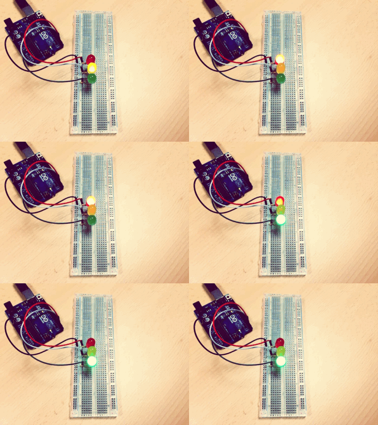
This task builds on the functions you saw in Blink and the electronics you have learned about this part , you must create a traffic light with three LEDs (one green on pin 4, one amber on pin 3, and one red on pin 2) which must light up in the following sequence:
- Green, lit for 3 seconds (the green LED must be the first one to light up)
- Amber, lit for 1 seconds (and the green light must turn off when the amber light turns on)
- Then finally the red light should be on by itself for 3 seconds
This sequence must be executed over and over while the Arduino is powered on.
Problem Statement
Based on the Arduino functions seen this part, your mission is to write an Arduino sketch that will blink 3 virtual LEDs (green→pin 4, orange→pin 3, red→pin 2). This program will must abide by the following instructions:
- All the pins have to be set as
OUTPUTat the beginning of the sketch - The green LED (on pin 4) is switched on for 3 seconds (green LED will be the first to light up) then it is switched off
- When the green LED is switched off, orange LED is switched on for 1 seconds then it is switched off again
- When the orange LED is switched off, red LED is switched on for 3 seconds then it is switched off again
- These instructions must run again and again in the
loop()!
You can post yor created solution for Lab 1 in our facebook group
Tools specific to electronics
Making and testing your assembly
We have seen that breadboards are an ideal choice for making a quick assembly or prototyping to test something, since they make it easy to plug in and rearrange components for testing.
In order to optimize everything, a supply of single-strand wire is often simpler than multi-strand, as it fits into the breadboard holes better. There are breadboard wire kits of different sizes and colors to make clean mounts. As some of you may have noticed, it’s the same type of wire that we have in our walls to carry telephone signals!
Once you’ve made your assembly, you may have to do some testing and debugging, to find out where and why it’s not working. A multimeter is good for measuring voltage and current, and it also has a diode tester and Ohm meter. They are inexpensive and easily found in regular hardware stores.
Finally, when your installation is complete and functional you may want to fix the components in place by mounting them on a dedicated board. If you cannot make your own printed circuit boards and / or do not want to spend a lot of money to make them, you can still solder your components onto “hole plates” (also called protoboard or veroboard).
Solder
Since we are talking about soldering, let’s see what that’s all about… Of course, everything begins with the soldering iron. For electronics work, an iron of thirty watts will be enough. It must be able to heat between 300 and 400 ° C if you want the solder to melt. Obviously, there are soldering irons available at many price points, ranging from the simple iron for $10 to an adjustable station that can cost more than $100. Choose according to your means and your needs, but keep in mind that the cheapest will heat slowly or hardly reach a sufficient temperature. In general, we do not recommend “pistol” type irons.
The soldering iron is pretty useless on its own – you’ll have to buy some solder (an alloy of tin and copper). Solder may or may not contain lead: lead makes it easier to solder, but must be used in a ventilated space because the vapor is bad for your body.
A desoldering wick or desoldering pump (‘solder sucker’) can also be useful but is not essential.
![Une station pour souder à température réglable (source : By User Smial on de.wikipedia (Own work) [FAL, GFDL 1.2 (http://www.gnu.org/licenses/old-licenses/fdl-1.2.html) or CC BY-SA 2.0 de (http://creativecommons.org/licenses/by-sa/2.0/de/deed.en)], via Wikimedia Commons)](http://upload.wikimedia.org/wikipedia/commons/thumb/5/5d/Loetstation_Weller_WTCP-S.jpg/574px-Loetstation_Weller_WTCP-S.jpg)
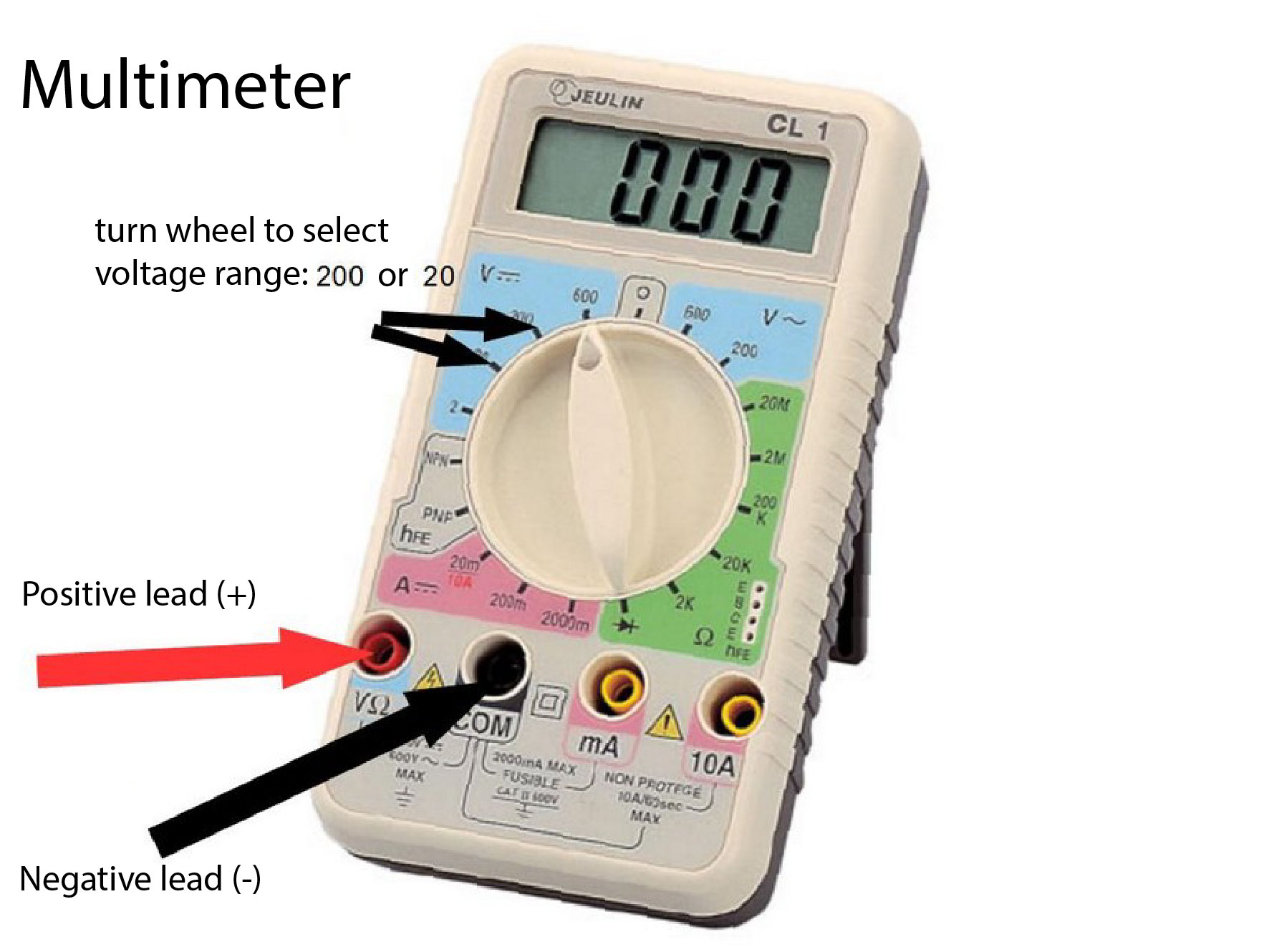
Voltmeter
The voltmeter is a device that makes it possible to measure the voltage (or electrical potential difference) between two points, whose unit of measurement is volt (V).
The vast majority of current measuring instruments are built around a digital voltmeter, the physical quantity to be measured being converted into voltage using a suitable sensor. This is the case of the digital multimeter which, in addition to offering the voltmeter function, includes at least one current-voltage converter to operate as an ammeter, and a constant current generator to operate as an Ohmmeter. (source: wikipedia)
Oscilloscope
An oscilloscope is a type of electronic test instrument that allows observation of varying signal voltages, usually as a two-dimensional plot of one or more signals as a function of time. Other signals (such as sound or vibration) can be converted to voltages and displayed.. The rendering curve of an oscilloscope is called an oscillogram.
Analog oscilloscopes use a direct input voltage (multiplied up or down) to produce spot deviation, and digital oscilloscopes transform the input voltage into a digital signal before it gets processed. In this case, the visualization of the signal is usually performed by a computer connected to the oscilloscope. (source wikipedia)
