Overview
In this lesson, you will learn how to control a servo motor using an Arduino.
Firstly, you will get the servo to sweep back and forth automatically and then you will add a pot to control the position of the servo.
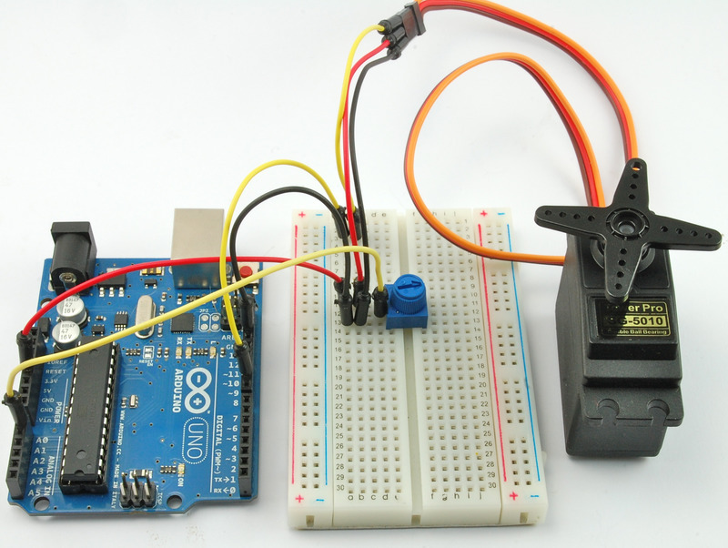
Parts
To build the projects described in this lesson, you will need the following parts
10 kΩ variable resistor (pot) , Breadboard , Arduino Uno R3 , Jumper wires

The Breadboard Layout for ‘Sweep’
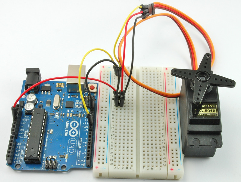
For this experiment, the only thing connected to the Arduino is the servo motor.
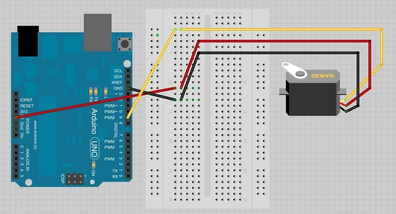
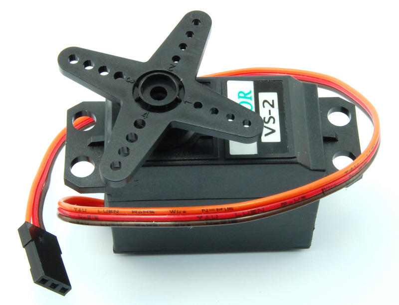
The servo motor has three leads. The color of the leads varies between servo motors, but the red lead is always 5V and GND will either be black or brown. The other lead is the control lead and this is usually orange or yellow. This control lead is connected to digital pin 9.
The servo is conveniently terminated in a socket into which we can push jumper wires, to link it to the breadboard and then to the Arduino.
If the Servo Misbehaves
Your servo may behave erratically, and you may find that this only happens when the Arduino is plugged into certain USB ports. This is because the servo draws quite a lot of power, especially as the motor is starting up, and this sudden high demand can be enough to drop the voltage on the Arduino board, so that it resets itself.
If this happens, then you can usually cure it by adding a high value capacitor (470uF or greater) between GND and 5V on the breadboard.
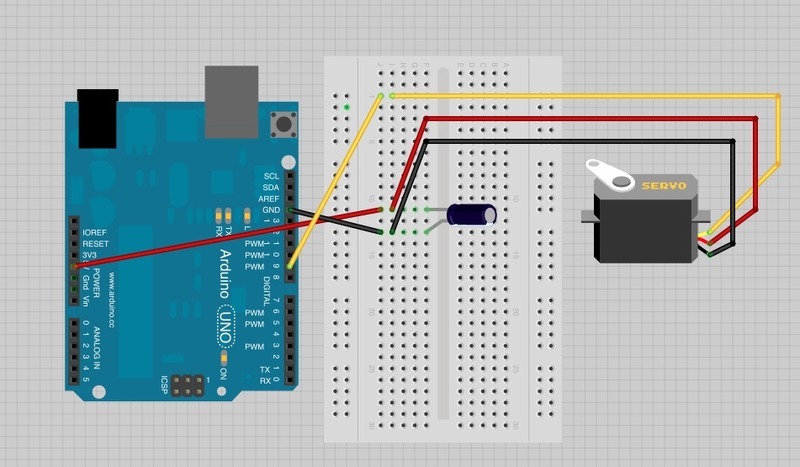
The capacitor acts as a reservoir of electricity for the motor to use, so that when it starts, it takes charge from the capacitor as well as the Arduino supply.
The longer lead of the capacitor is the positive lead and this should be connected to 5V. The negative lead is also often marked with a ‘-‘ symbol.
Arduino Code for ‘Sweep’
Load up the following sketch onto your Arduino. You should find that the servo immediately begins to turn first in one direction and then back in the other.
The sketch is based on the standard ‘sweep’ sketch that you can find in the Arduino Examples under the folder ‘servo’. You can if you prefer just run that sketch.
/*
Adafruit Arduino - Lesson 14. Sweep
*/

#include <Servo.h>

int servoPin = 9;

Servo servo;

int angle = 0;   // servo position in degrees

void setup()
{
  servo.attach(servoPin);
}


void loop()
{
  // scan from 0 to 180 degrees
  for(angle = 0; angle < 180; angle++)
  {
    servo.write(angle);
    delay(15);
  }
  // now scan back from 180 to 0 degrees
  for(angle = 180; angle > 0; angle--)
  {
    servo.write(angle);
    delay(15);
  }
}
Servo motors are controlled by a series of pulses and to make it easy to use them, an Arduino library has been created so that you can just instruct the servo to turn to a particular angle.
The commands for using a servo are like built-in Arduino commands, but because you are not always going to be using a servo in your projects, they are kept in something called a library. If you are going to use commands in the servo library, you need to tell the Arduino IDE that you are using the library with this command:
#include <Servo.h> As usual, we then use a variable ‘servoPin’ to define the pin that is to control the servo.
This line:
Servo servo; defines a new variable ‘servo’ of type ‘Servo’. The library has provided us with a new type, like ‘int’ or ‘float’ that represents a servo. You can actually define up to eight servos in this way, so if we had two servos, then we could write something like this:
Servo servo1;
Servo servo2;
In the ‘setup’ function we need to link the ‘servo’ variable to the pin that will control the servo using this command:
servo.attach(servoPin); The variable ‘angle’ is used to contain the current angle of the servo in degrees. In the ‘loop’ function, we use two ‘for’ loops to first increase the angle in one direction and then back in the other when it gets to 180 degrees.
The command:
servo.write(angle); tells the servo to update its position to the angle supplied as a parameter.
The Breadboard Layout for ‘Knob’
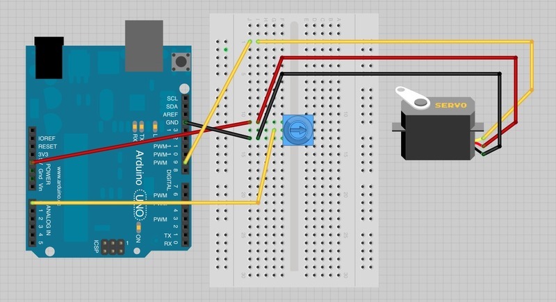
Our next step is to add a pot so that we can control the position of the servo by turning the knob.
You just need to add the pot and a lead from its slider to A0 on the Arduino.
Arduino Code for ‘Knob’
The code to make the servo follow the knob’s position is simpler than to make it sweep.
/*
Adafruit Arduino - Lesson 14. Knob
*/

#include <Servo.h>

int potPin = 0;
int servoPin = 9;
Servo servo;

void setup()
{
  servo.attach(servoPin);
}

void loop()
{
  int reading = analogRead(potPin);     // 0 to 1023
  int angle = reading / 6;              // 0 to 180-ish
  servo.write(angle);
}
There is now a second variable called ‘potPin’.
To set the position of the servo, we take an analog reading from A0. This gives us a value of between 0 and 1023. Since the servo can only rotate through 180 degrees, we need to scale this down. Dividing it by six will give us an angle between 0 and 170, which will do just fine.
Servo Motors
The position of the servo motor is set by the length of a pulse. The servo expects to receive a pulse roughly every 20 milliseconds. If that pulse is high for 1 millisecond, then the servo angle will be zero, if it is 1.5 milliseconds, then it will be at its centre position and if it is 2 milliseconds it will be at 180 degrees.
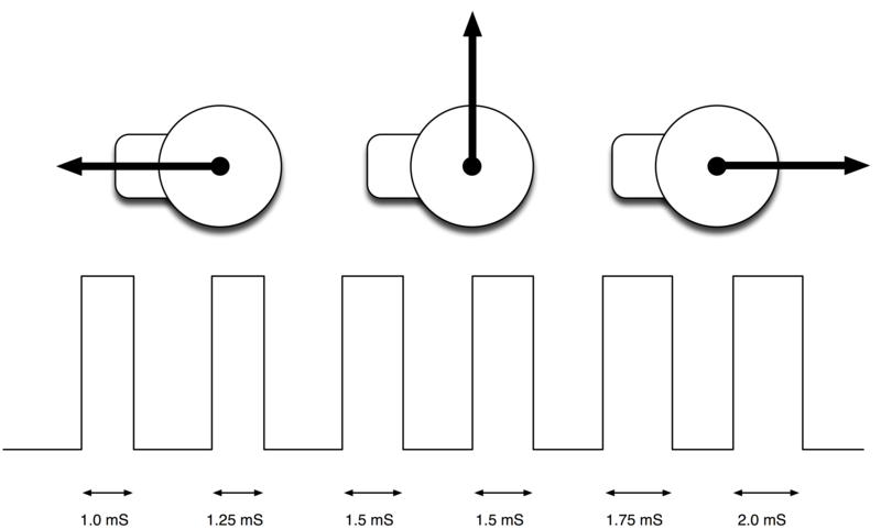
The end points of the servo can vary and many servos only turn through about 170 degrees. You can also buy ‘continuous’ servos that can rotate through the full 360 degrees.
Inside a Servo
The following short video shows you what is going on inside a servo.
Beware though, if you dismantle your servo like this, there is a good chance that it will not go back together properly.
Other Things to Do
Open the ‘sweep’ sketch and try reducing the delays from 15 milliseconds to say 5 milliseconds. Notice how much faster the servo turns.
Try modifying the ‘knob’ sketch so that instead of taking the servo angle from the position of the knob, it takes it from the Serial Monitor, so that you can control the servo from your computer.
Hint: to make your sketch read the number of degrees from the Serial Monitor, you can use the function Serial.parseInt(). This reads a number from the Serial Monitor.
